Transmitting Data Through Air: Radios
- Introduction
Have you ever wondered how wireless communication is achieved? How radio waves are used to transmit data through long distances? In this article, we will go through a brief history of radio technology, how they are invented, how they are used today, and how you might be able to build your own functional radio.
Why We Use Radio Waves:
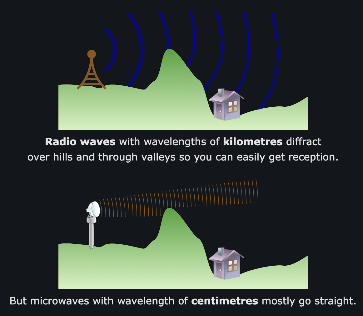
Out of the electromagnetic (EM) spectrum, radio waves have the lowest frequency and longest wavelength out of every other EM wave. Radio waves are any EM waves below 300 kHz, and they are around or above 1 mm in wavelength. At such a low frequency, the waves do not carry enough energy to knock off electrons from atoms, therefore they are not ionizing and they do not harm the human body (at the low power that it is transmitted at. At very high powers, dielectric heating may occur). Unlike microwaves, which have a slightly higher frequency (and shorter wavelength), radio waves rarely have enough energy to cause internal cell heating, therefore they are safe to transmit. The long wavelength of radio waves allow for a larger degree of diffraction, so radio waves are able to diffract over large barriers like mountains (see Fig. 1). Additionally, radio waves are able to reflect off of the ionosphere (top layer of the atmosphere that contains lots of charged particles due to solar radiation), which helps transmit signals to its destination. Lastly, radio waves are able to pass through most obstacles such as brick walls and glass, allowing data to be sent to indoor areas. Although metals are able to absorb radio waves, it is not a serious concern since large metal surfaces are incredibly uncommon. This is also why the antennas of radios we use are made of metals. Microwaves, on the other hand, are absorbed by a very large wide range of materials, hence they are not optimal for long range data transmission.
- FM vs AM:
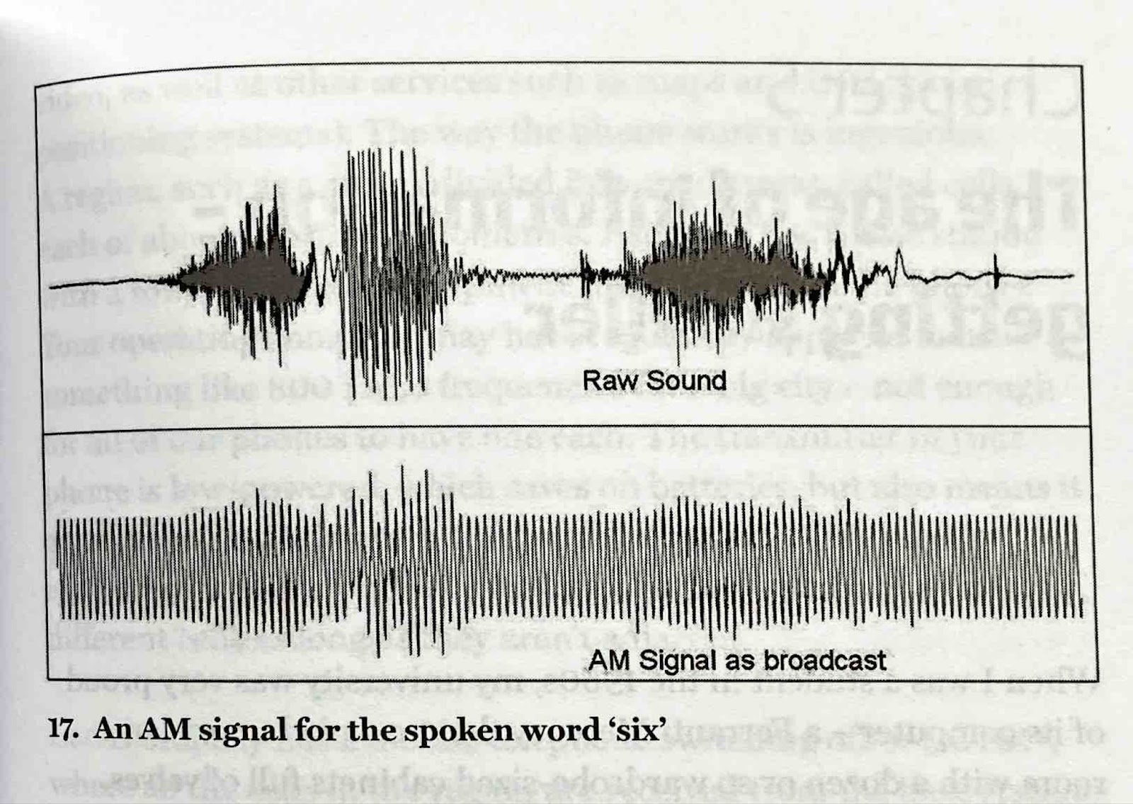
Through modulation and demodulation, we are able to utilize the properties of waves to transmit information. Data could be coded in 2 ways, by modulating the wave’s amplitude or frequency. This is the AM (amplitude modulation) and FM (frequency modulation) settings of our radios. When a radio station is using AM, the waves transmitted will have a varying amplitude, but the frequency of the wave will remain the same and vice versa (see Fig. 2). AM tends to have a lower sound quality than FM because they have a lower bandwidth (maximum amount of data that could be sent per second), but it is easier and cheaper to make and transmit data. AM waves are also affected by loud noises, which may cause a disruption in its amplitude, hence data might be lost. FM waves might be affected by physical barriers, but they are less likely to be affected by other waves. AM waves operate a lower frequency (~530-1700 kHz) than FM waves (~90-100 MHz).
- The Genesis of Radios:
The invention of radio technology stems from the discovery of EM waves by Heinrich Hertz in 1887. After its discovery, a few countries like Russia and the United States were working on wireless communication, but the Italian inventor Guglielmo Marconi was the first to achieve success. He started conducting research on wireless communication in 1894 in his attic, and managed to send a morse code message through a distance of around 2 kilometers. Some were skeptical of the practicality of radio, with the Scottish physicist and mathematician, Sir William Thomson (later known as Lord Kelvin) claiming that “Radio has no future”. There were also doubts regarding if radio waves are reliable for long distances due to the curvature of the earth, but Marconi disproven the doubts by sending the letter “s” in morse code through the Atlantic ocean, from England to Canada. He later won a joint nobel peace prize in 1909 in physics with Ferdinand Braund, a German radio innovator. In 1937, on the day of his funeral, all BBC channels went silent for 2 minutes to commemorate his death.
Regulations Regarding Radios:
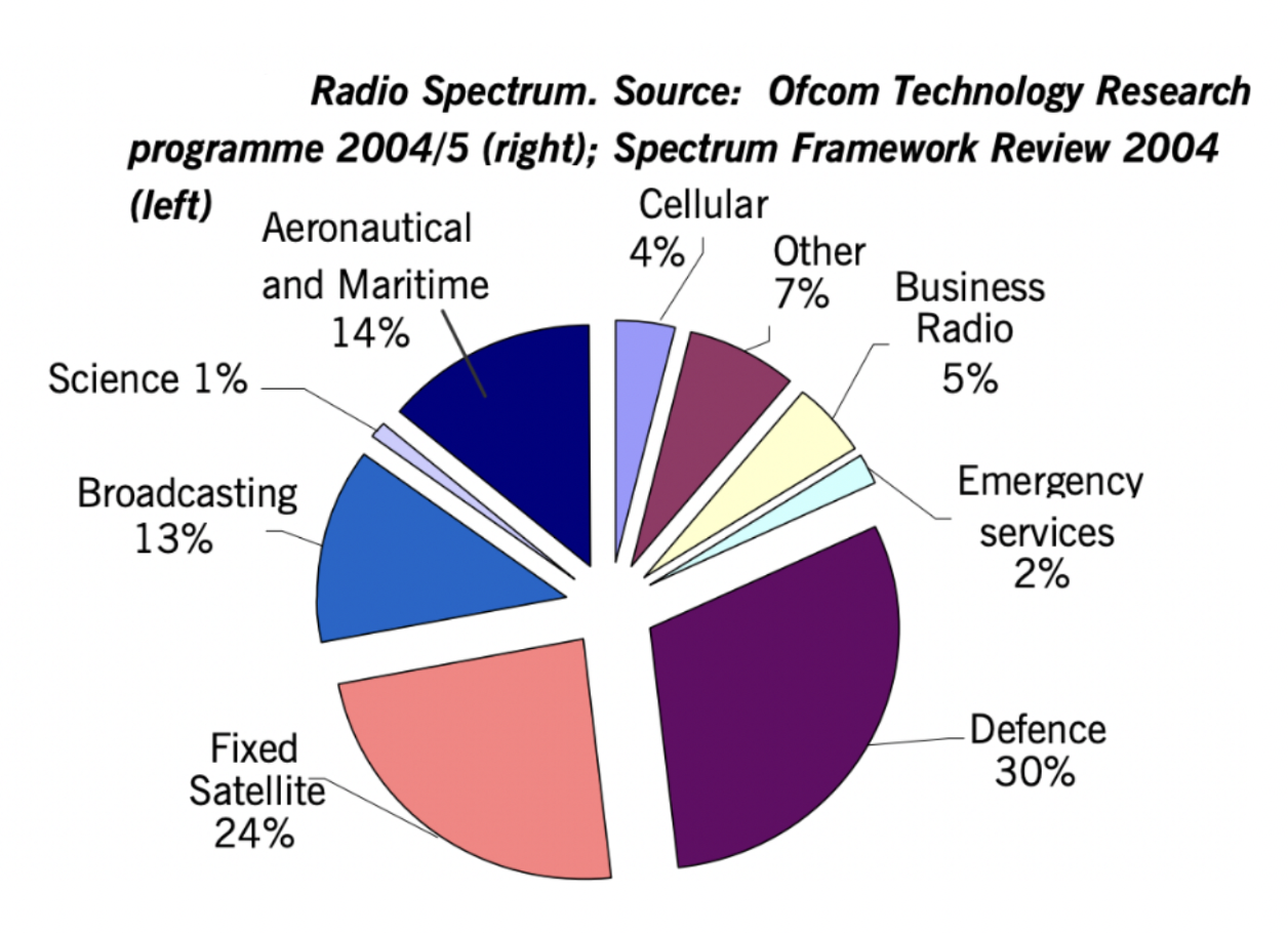
Since the world wars, radio has been used for all sorts of essential matters such as emergency services and national defense (see Fig. 3). As said by one of the teachers helping me with this article, “If you make a radio transmitter too strong, you are going to make some very important people very angry”. Therefore, it is no surprise that the government decided to regulate the use of radio transmitters to reduce the interference of radio waves. Ofcom, the UK’s communication regulator ensures the minimization of interference between radio waves by issuing licenses to users. Short range walkie-talkies that output less than 0.5 W of power do not require a license, but anything stronger than that will. There are different types of licenses available at different price ranges. The most basic one allows you to share a specific frequency with other users anywhere in the UK; The more expensive one dedicates a specific frequency to users in a limited area; and the most expensive one is intended for radio suppliers to sell radio equipment.
- How Does a Radio Work?
1. A brief, simple overview
For simplicity, the type of radio outlined in this article is an AM crystal radio. There is another type of radio known as a transistor radio. Although it is more complicated to build, it can detect AM and FM signals that are weak. Crystal radios got its name from the diode used in it, originally known as a crystal detector.
With many channels playing, there are many radio waves of different frequencies traveling through the air at the same time, so how does a radio pick out a specific channel to play? The solution is to filter out all other channels, leaving the desired frequency to be played by the radio. When tuning a radio to an AM channel, you are tuning a radio to a specific frequency known as the carrier frequency, and the amplitude of the radio waves obtained from that specific frequency will be the data that is sent through the wave.
Since the explanations might be confusing, I will explain the main mechanisms without going into much depth first. The antenna receives radio waves of all sorts of frequencies from radio stations, from which a specific carrier frequency gets filtered out by an inductor and a variable capacitor. Then, the signal will be cleaned up by a diode and a capacitor, and finally, the clean signal is sent to the speakers to be played.
- Tuning
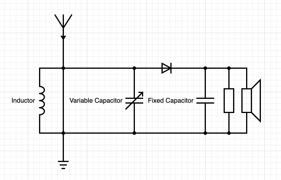
Surprisingly, the only power source a crystal radio needs to operate on is the EM waves transmitted from radio stations. Without any other power source, the energy is only sufficient to sound the speakers of earbuds. To use a crystal radio with larger speakers, an op amp is needed to provide additional power. The EM waves cause the electrons of the antenna to vibrate, creating a varying current in the wire. The vibrations are filtered out by the inductor and variable capacitor that are tuned to pick up a specific frequency of frequency of current in the wire. The current of the wire connected to the antenna creates a magnetic field that causes an EMF in the wires of the inductor, which helps pick out a specific frequency.
If you have never come across capacitors and inductors before, here is a brief summary of these two components. A capacitor has 2 sides, one positively charged, and the other negatively charged. It charges up until one side is full, then it can discharge, releasing the stored charge. An inductor is a bunch of wires wrapped around a ferrous metal, and when a current passes through it, the metal gains a magnetic field that causes EMF in the wires.
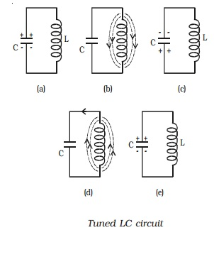
The mechanism for tuning the radio, involving the variable capacitor and the inductor is known as a resonant circuit. Without going into much detail, the variable capacitor discharges and a current is passed through the inductor to the other side of the capacitor. An EMF of the opposite direction is created in the inductor, which forces the charge to move back to its original side of the capacitor. This cycle repeats indefinitely and the induced current moves at a different frequency.
As the induced current varies and oscillates, and the frequency of the oscillation is known as the resonant frequency. The resonant frequency depends on the capacitance of the variable capacitor; Henceforth, by adjusting the capacitance, the resonant frequency and only the resonant frequency of the EM wave will be picked up. When the resonant frequency and the carrier frequency of a channel matches, the radio will be tuned to that channel. Since the signal is modulated in AM, the actual data is stored in the amplitude of waves of the carrier frequency.
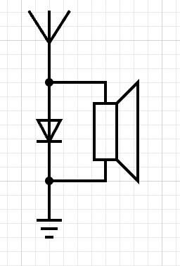
- Rectifying the Signal
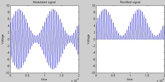
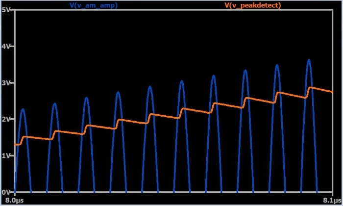
Moving on from tuning, the signal of the carrier frequency will be passed on to the diode. An EM wave has a positive and negative voltage portion, since the electrons are moving back and forth. A diode allows electrons to travel in 1 direction, therefore the negative or backwards portion of the EM wave is eliminated (see Fig. 6). The additional fixed capacitor and resistor after the diode helps smooth out the audio signal. This configuration is known as a “peak detector”, since it outputs only the peaks of the input signal (see Fig. 7). The output will be sent to a speaker that “translates” the signal into speech and music with the vibrating diaphragm.
With only the diode and no resonance circuit, the radio could still theoretically function, but it cannot be tuned (see Fig. 8). This results in the speaker playing every channel that the antenna detects, which is not exactly ideal with the copious amount of channels playing at the same time in the modern day (you will hear the strongest signal that the antenna receives most prominently).
I understand that reading may not be the most effective way of interpreting how electrical systems work, so for a visual representation and another explanation of the resonance circuit, I highly recommend the video “How a Crystal Radio Works” by RimstarOrg on YouTube.